Feel free to hang out and lurk as long as you like. However, we would like to encourage you to
 - Joined
- Feb 28, 2003
- Messages
- 51,246
- Reaction score
- 8,254
- Location
- Huntsville
- First Name
- Scott
- Last Name
- Friday
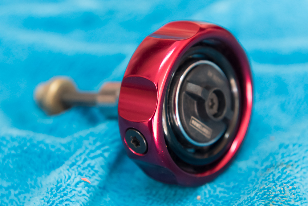
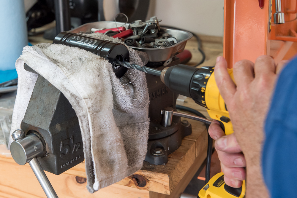
Special tool for removing fork caps.

Fork oil gets dumped in oil pan, pretty black...

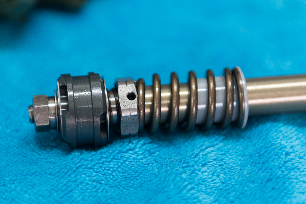
Shim stack for rebound damping?

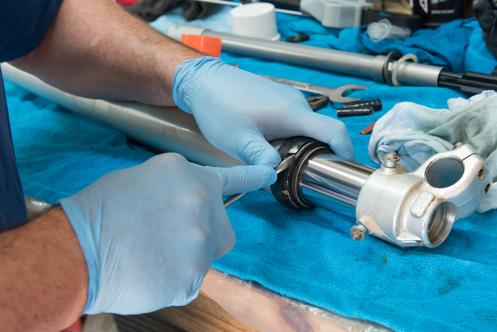
Cleaning all the internals

Oil gets shoved through holes in the body of this piece and has to push past the shims which restrict the flow. Thicker or thinner shims make it harder or easier for oil to flow. Adjusting once assembled allows oil to bypass the "valve" so oil flows easier. More flow means fast rebound, less flow means slower rebound. Rebound is the extension of the fork after a compression stroke.

Compression valves? It got sprayed but not disassembled. Work on the same principle as the rebound valves by controlling the flow rate of the oil. More flow means softer feeling hit at the bars (longer stroke) and better bump absorption. Less flow means harder feeling hit (shorter stroke) and less bump absorption.
Special care must be taken when freeing the seals so that you don't accidentally nick or scrape the slider. That would be BAD as it would lead to premature wear of the new seal!
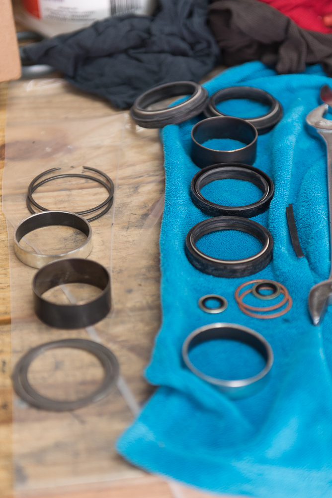
Bushings and seals on slider

Unless you really know what you are doing, it is a good idea to REALLY pay close attention to the order in which these parts come off the slider. This is where a little point and shoot digital camera comes in handy for those of us with poor memory skills...

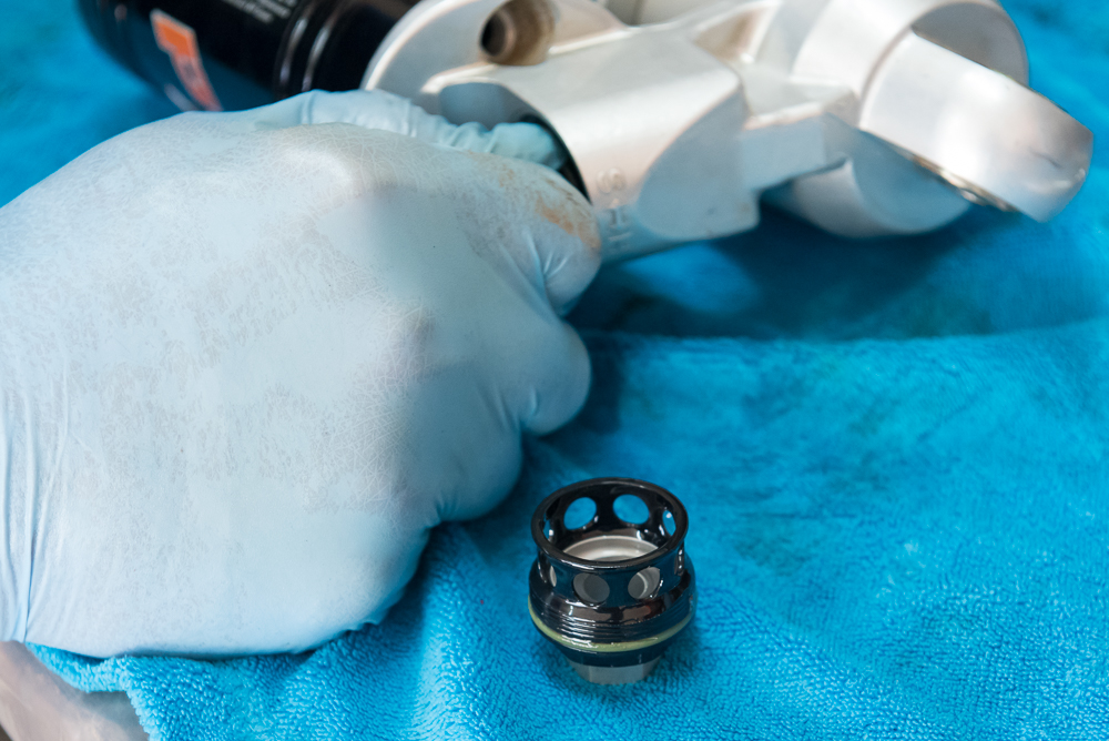
New bits waiting for installatoin
Another special tool to prevent tearing of seals as they are pushed over the end of the slider.

Special tool for seating the seals

Fork reassembled, new oil is added and the fork is repeatedly compressed and extended to bleed it before checking for proper oil level.
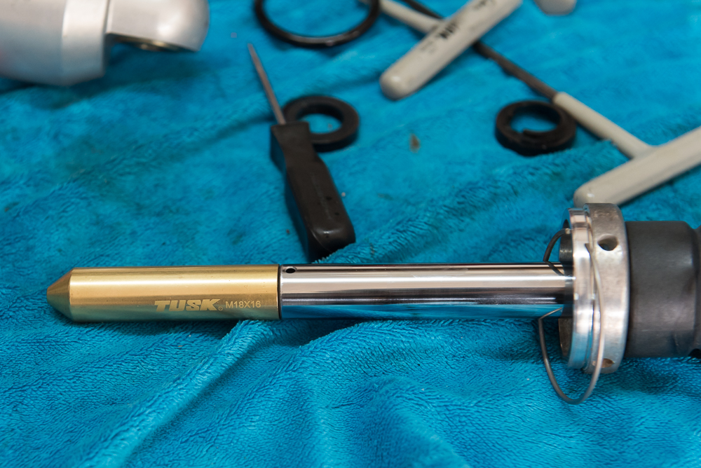
Special tool for setting proper oil level. When I did this on my KLR 650 years ago, I was dipping a wooden dowel into the fork and trying to measure how deep it was from the top of the fork. It was a total pain. This tool is awesome. Simply set the desired depth level on the gauge etched on the tube, set the cap on the top of the fork, suck until you get air. Easy peasy!!


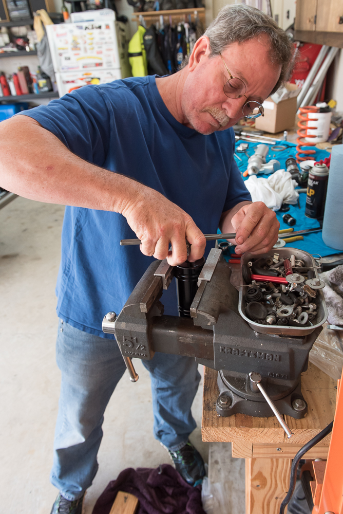
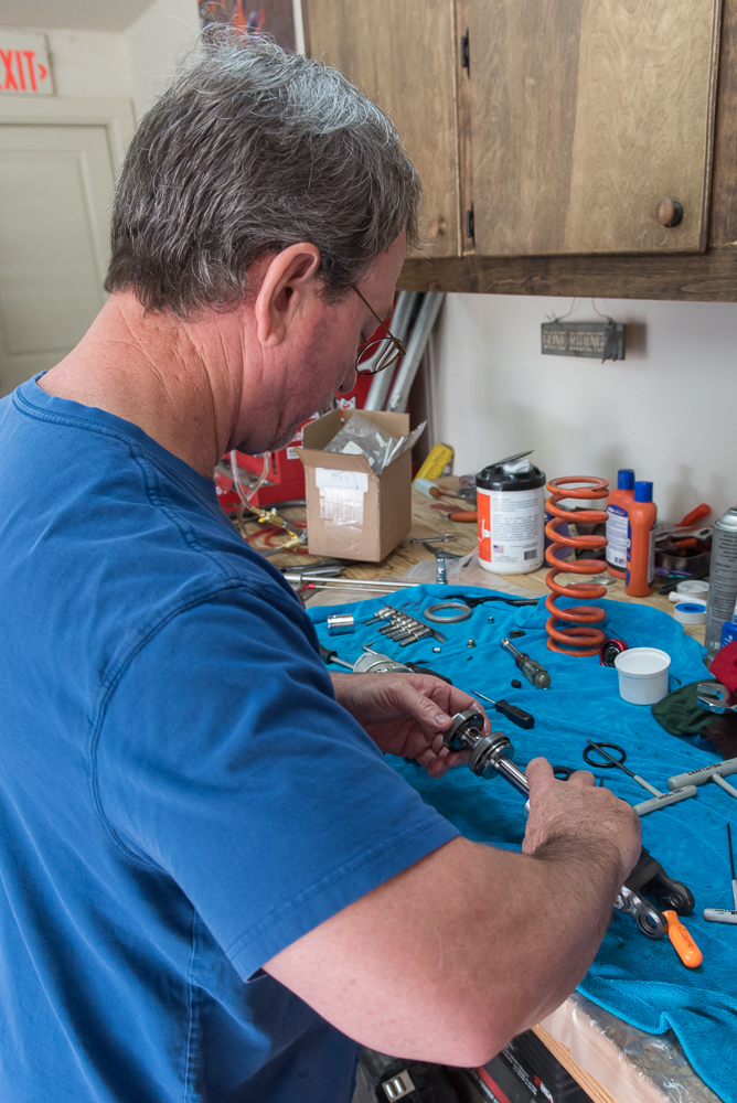
First step, release the preload on the spring after measuring so we can get it back to the right spot after reassembly. This requires a spanner wrench.
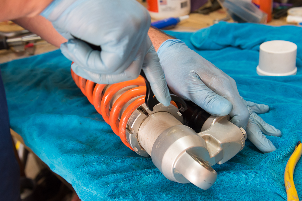
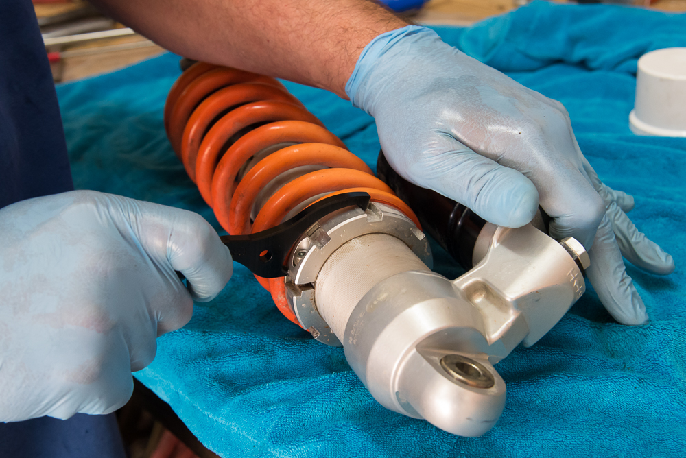
With the compression load off the shock, the restraining clip is removed.

The normal KTM procedure does not involve releasing the Nitrogen. However, we will be doing that and checking the condition of the reservoir and the piston. Here the Nitrogen is CAREFULLY released.
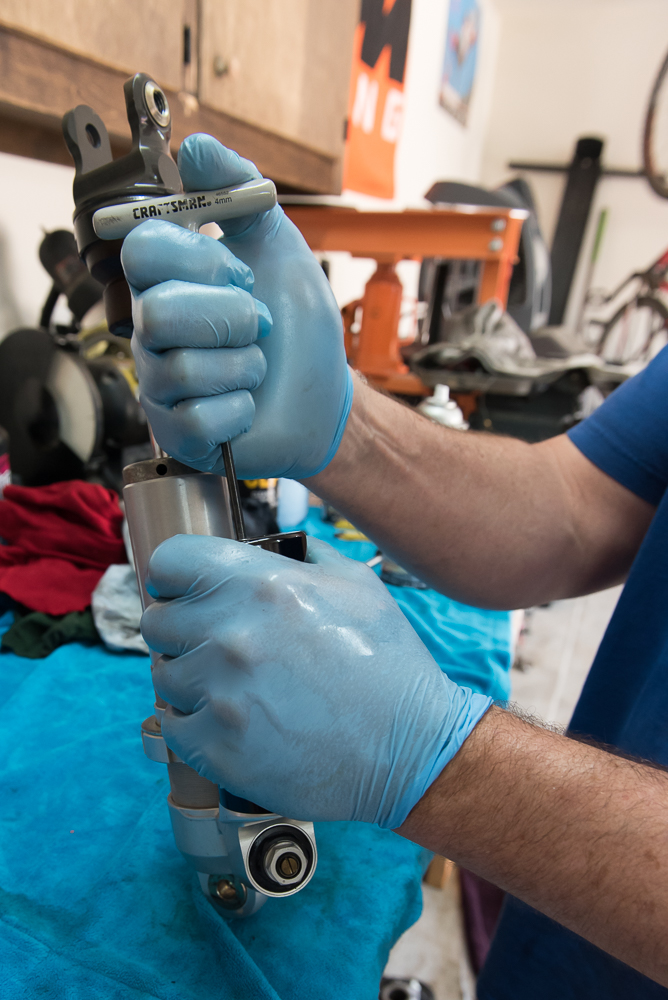
Time to remove the slider from the shock body

This is one of Roger's LITTLE drift pins... Seriously

He works his way around the cover, popping it off a little at a time at each point until the whole piece comes off.

The screw at the top of the reservoir here is where the oil is drained.

Another cool special tool! A ratchet on two gimbals. Used to remove the plug screw.
Draining the oil. Doesn't look horrible, but definitely not new.

The orangish brown rubber piece at his right hand gets replaced. It is a bumper to protect the pieces in case the shock gets totally compressed.

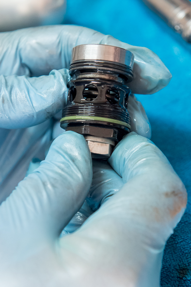
Cover on far right, then retaining ring, sealing o-ring, then the valves with slider bushings around the outside of them.
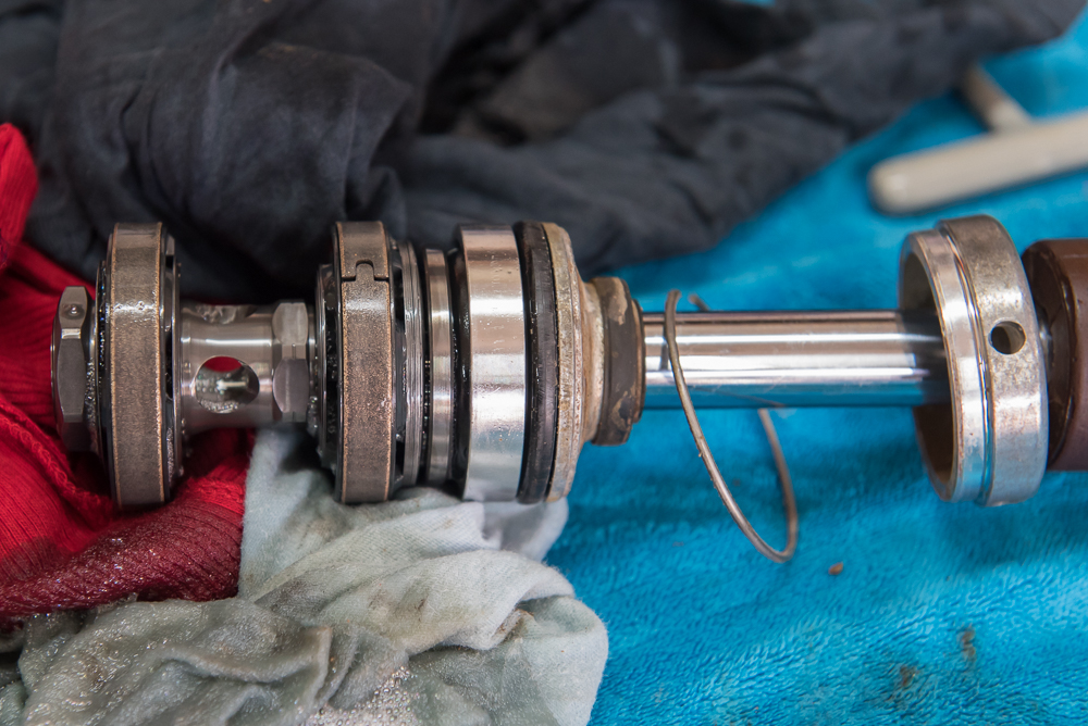
You can see the different diameter and thickness of the shims here. The combined stack acts like a circular cantilevered beam that is fat at the wall and tapers to a point out at the edges. It flexes easier and quicker and then gets progressively stiffer and more flow resistant as more oil tries to push through. We don't mess with the shims and valves other than to spray clean them. They aren't really wear items like the seals and bushings.

Roger removes the adjustment valve between the main shock body and the reservoir. Adjusting this fine tunes the flow of oil between the body and reservoir.

The cover
The valve. Adjusting it simply lets oil bypass the valve for more flow.
VERY important step. Roger is pushing the piston to the FAR side of the reservoir. Removal of the reservoir requires heating it around the threaded end to get it to release. We DON'T want to burn the o-ring on the outside of the piston!!

SOME of Roger's special tools...

Shock body in bench vise prior to heating the reservoir

Heating gun, another tool I do not have...

It doesn't take much, so you have to be careful. You don't want to get it too hot. I think Roger had the gun on low and only heated it for maybe 10-15 seconds as he was going around the circumference of the body.

There's a special tool here, but it is black and you might not spot it

It is the piece between the socket and the reservoir body

Here it is. It fits onto the end of the reservoir body so you can torque it to break the threads loose. Without this, you'd be forced to use some kind of clamp or BIG wrench on the body itself which would risk deformation of the body and impede the free movement of the piston. A bad thing!

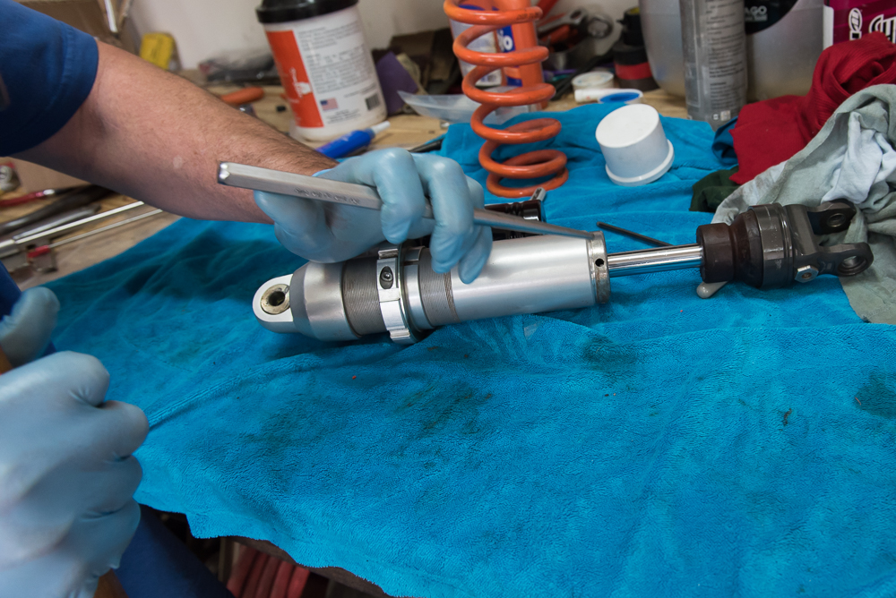
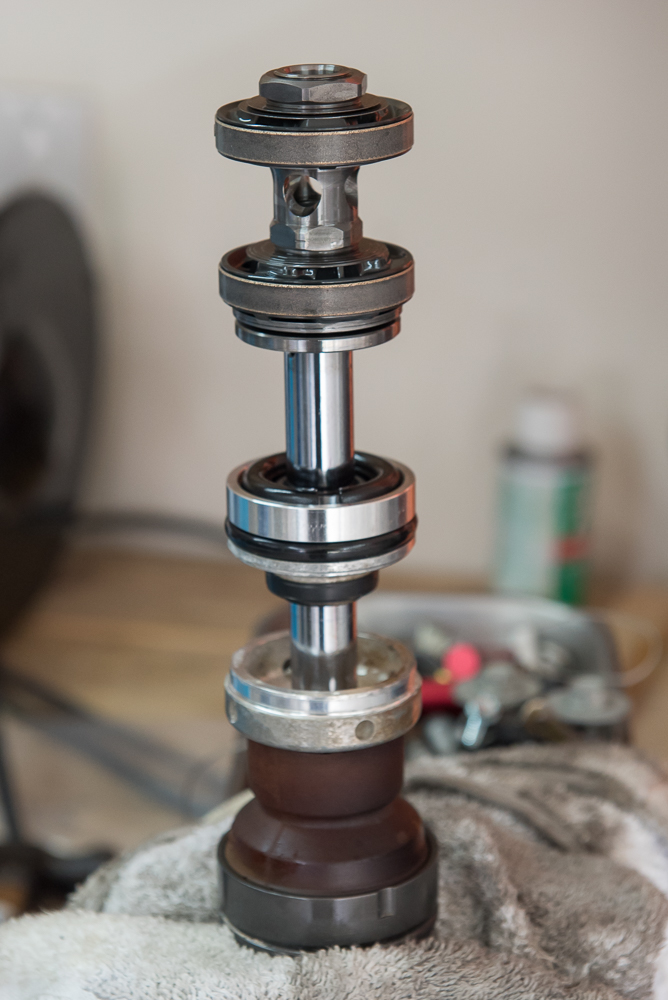
Now we turn our attention to the slider, valves, bushings and seals
Not a great shot, but I was trying to show the shims

There are a lot of parts when this all comes off the slider. Slipping it all over the end of this pick keeps everything in the proper order for reassembly.
New and old bumpers. You can see a bit of deterioration on the old bumper. But otherwise it is still in pretty good shape.

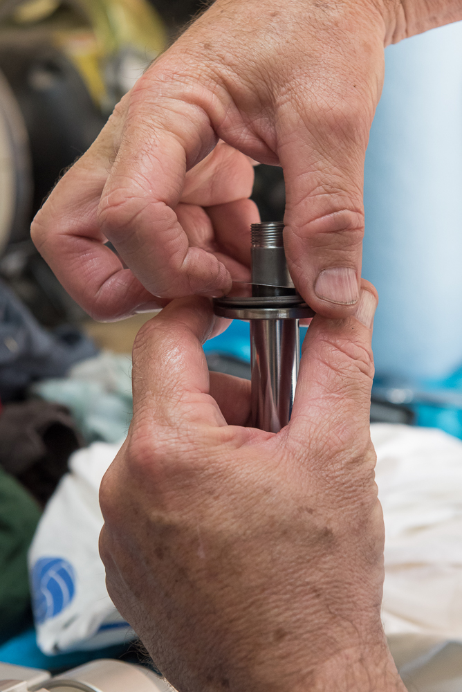
This is the end cap. It has an o-ring around the outside that seals against the inside diameter of the shock body and the brown bushing shown here where the slider goes through.

Special tool: slide hammer for pulling out that interior bushing shown in the above picture.

A couple of whacks and the bushing pops right out

Yet another special tool for getting the new bushing in place

No, not the socket...

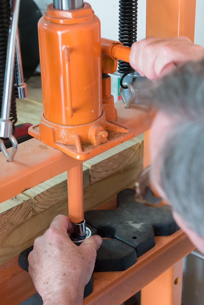
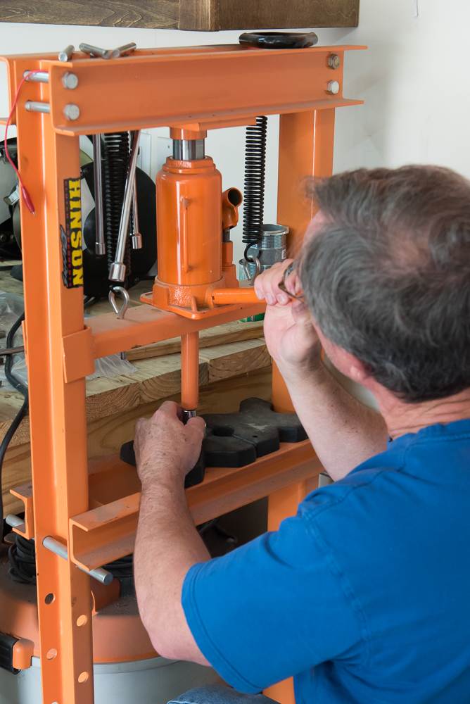
The hydraulic press. I am sure you could use a rubber mallet and a little block to tap the bushing into place, but this worked really well and allowed Roger to watch every step of the way to make sure the bushing was not getting tweaked to one side or the other.
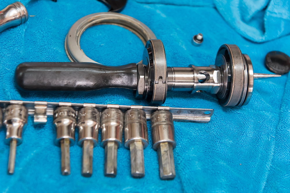
This tool is like the larger one used on the forks. It allows everything to slide easily back onto the slider without risking the tearing of new seals and bushings.
Then it is simply a matter of slipping everything off the pick back onto the slider.

Roger lifts one of the shims so I can show how thin they are
Here is a better pic showing the different diameters of the shims.

Locking everything back in place

With the shock internals back together, he turns his attention back to the reservoir and piston, giving both a good cleaning.

Never seen this before. Roger loves it and has been using it forever. It works great so it must destroy the planet... I can't believe it is still legal

Maybe a drill press might be better for absolute straight drilling, but Roger gets the job done nicely by hand.


Oh yeah, that will be getting a GOOD cleaning before reassembly!!

Now comes the tapping
I don't have a decent set of taps


Beautiful!
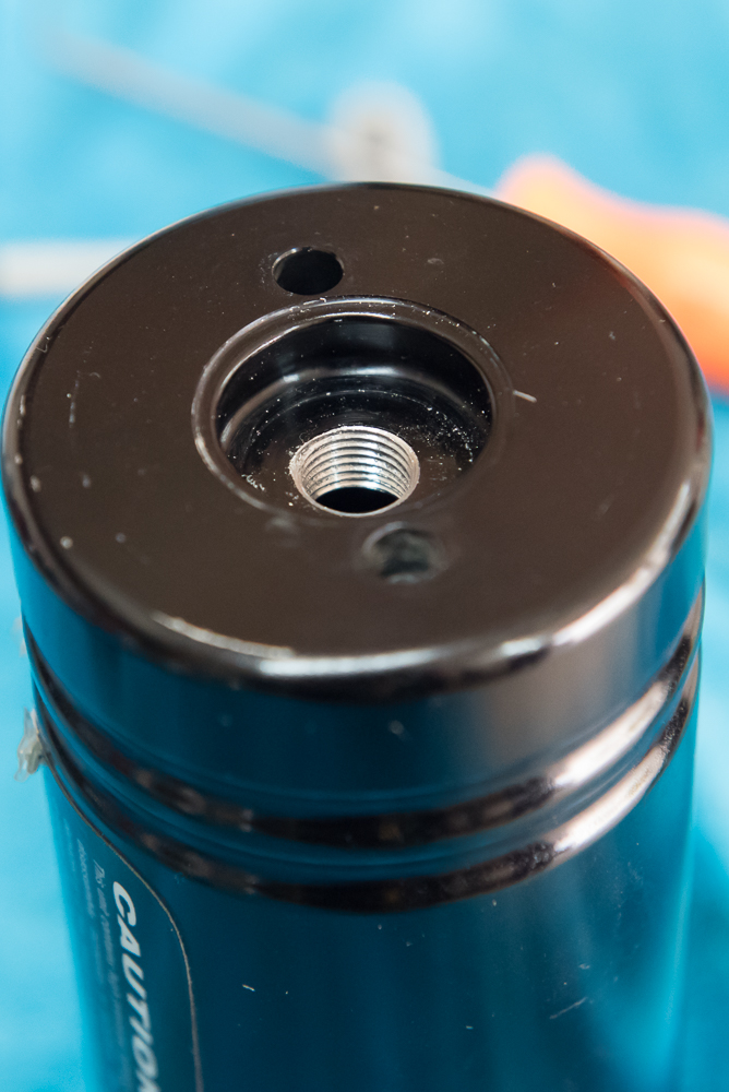
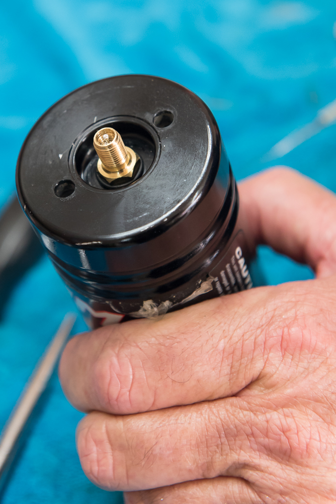
Shiny new schrader valve installed after everything is cleaned. It got a wrap of Teflon tape around the threads before being screwed in place.
Piston goes back into reservoir. Pay attention to orientation!

Special tool used again to reinstall reservoir. No torque value given. If I remember right, blue Loc-Tite is used and it is snugged firmly.

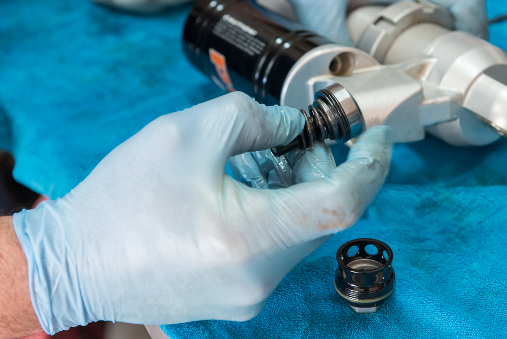
New bushings installed on outside of valves
That gold part is a special tool for driving the end cap back into place without tearing up the outer seal.

Behold a work of art

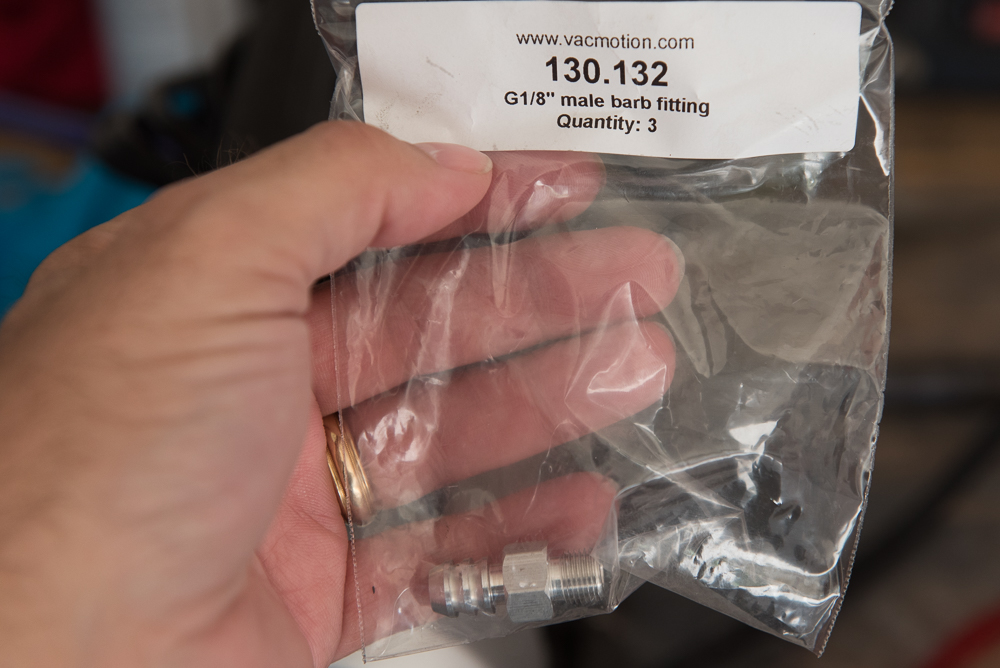
Here it is for those that might be interested. They come in a pack of three. The corners of the hex had to be filed down a bit to avoid contact with a lip around the hole in the body so it would fit down into the threads.
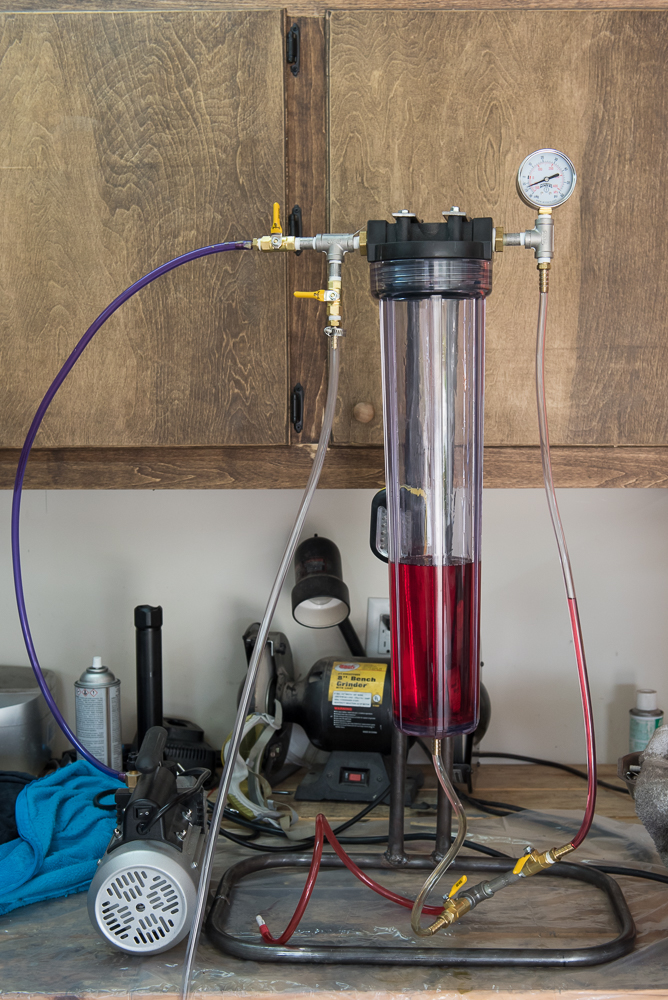
Here's the vacuum pump. It sucks...

The pressure gauge on upper right. Note that is also shows vacuum.

Roger pushes the left over oil from his shock into the bottle using positive pressure from the compressor.

Now he uses the vacuum to suck my new oil into the canister. At this point, the valve going to the bottom of the canister is closed and the return line is open to the top of the canister.

The oil REALLY foams up. At first, I am thinking we'll be here a while waiting for all the foam to go away.

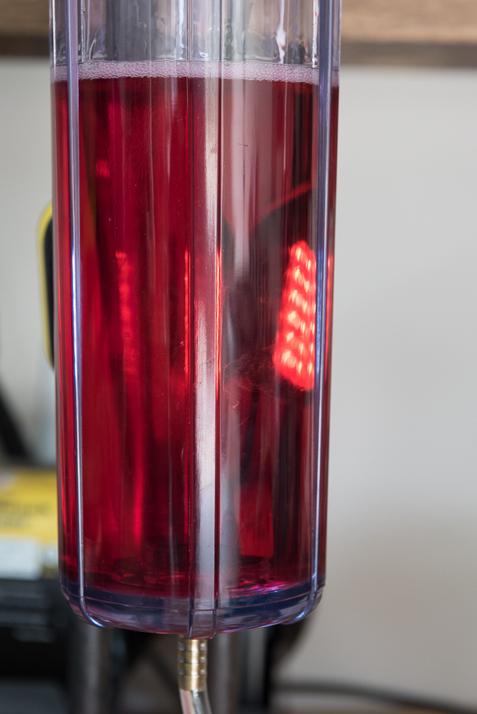
However, once the contents of the bottle have been transferred to the canister, Roger closes the return valve and subjects the canister to an increasing vacuum and the bubbles are quickly collapsed!
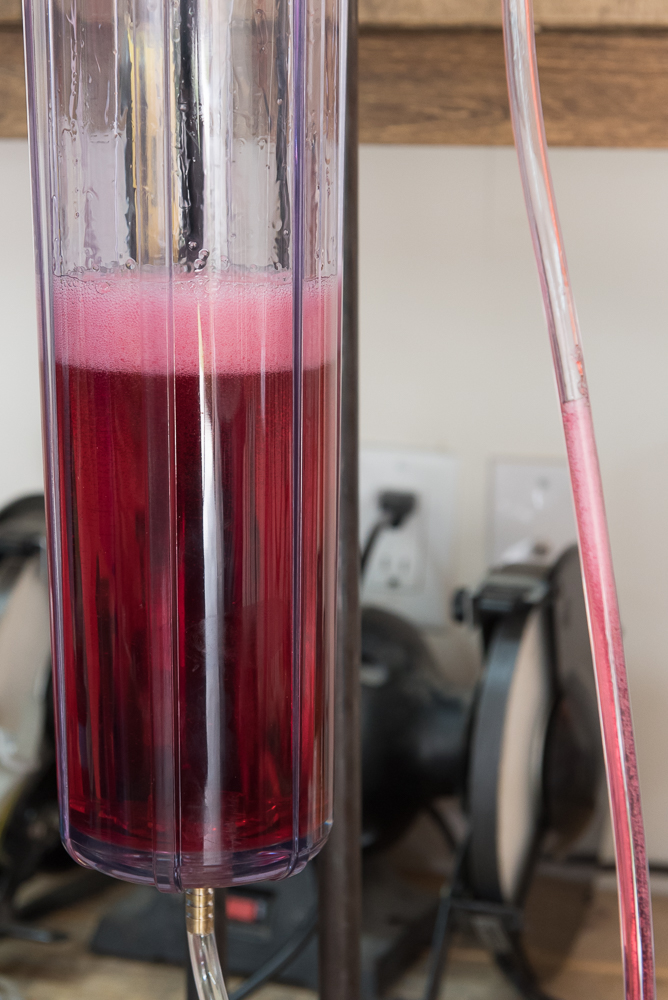
Getting to this point took maybe 15-20 seconds.
Ready for action. Clear hose on left goes to compressor under the work bench. The funky fitting for the shock body is in the end of the red hose under the canister.
Connected to the shock. Note that at this point, there is still no Nitrogen in the shock reservoir. We want the piston to move freely as oil goes in and out of the shock.
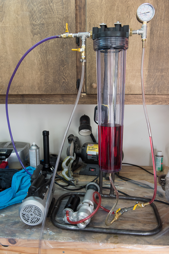
We set the shock down below the level of the work bench to stretch out the tube and to facilitate the rapid flow of bubbles up the line to the return valve.

A final check before starting.


 One occurred right at the LAST moment when Roger fortunately realized we messed up a VERY IMPORTANT step. We were lucky he realized it then and not after I got home and told him the bike was riding like crap!! Then there was that hose leaking right before it popped off and started spraying oil all over the place
Here he slides a long T handle Allen wrench into the reservoir to once again check its location with where we noted it before removing it.

See the bar along the side of the reservoir body? Just right.


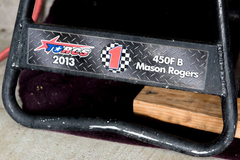
He races TORCS occasionally

And so does his son Mason
It went quicker the second time around and we were soon back to where he realized we had missed a step before. Here he's putting the drain/fill plug back in place before wiping everything down and taking a break.

Shop guard dog... SPOILED like you wouldn't believe, hehe.
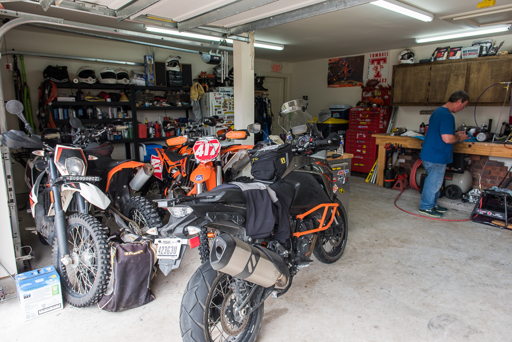
Roger and Mason's rides
Okay, time to charge the Nitrogen for the reservoir. I won't reveal his sources for Nitrogen.
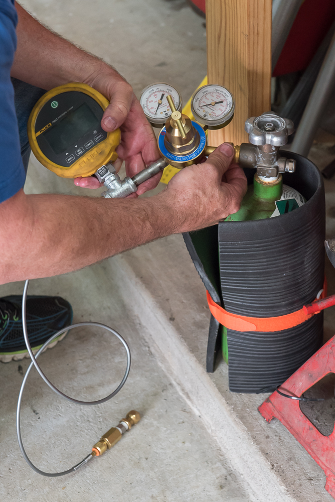
Nice digital gauge!

He sets it for 150 psi.

Charging the reservoir
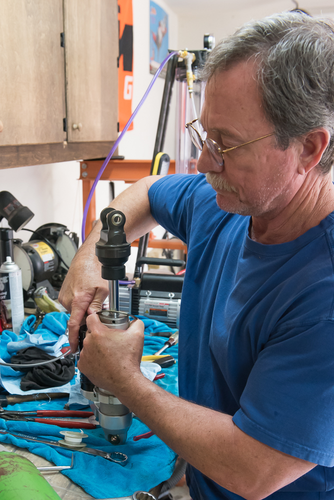
Getting ready to remount the spring

Roger's wife, Lisa, a VERY understanding woman

The lovely couple, sweet hearts from a young age.