• Welcome to the Two Wheeled Texans community! Feel free to hang out and lurk as long as you like. However, we would like to encourage you to register so that you can join the community and use the numerous features on the site. After registering, don't forget to post up an introduction!

Stebel Nautilus Installation

My installation from some old pictures:

The empty right side cowl showing the space to work with:
emptycowl0798q.jpg


The airhorn in place:
airhorn0802q.jpg


The front of the bike - the horn is just below the right turnsignal - it has a white circle of velcro to stick to the cowling plastic.
d70_0055q.jpg


Closeup of the horn installation - the tubular frame has the relay zip-tied to it. The hose clamp is hidden but attaches to the same tube but where it is nearly vertical rather than angled.
d70_0061q.jpg


You can get larger versions of the photos by clicking on these.

Hope that helps give you some ideas. I'm tempted to put a second horn on the left side... :trust:

Thanks for the pictures, I'm contemplating putting a pair of horns in my Wee, and was eyeing that exact location.
 
A few more installation pics:

Here is the threaded frame hole that I bolted into. It was very thoughtful of Suzuki to provide this!

This picture shows how the fuel tank can be raised on blocks, without disconnecting the hoses, to run the electrical wires for the new horn:


Now I'm making sure the bracket is plumb before I bolt the horn to it. You know the rule: measure twice and cut once.


And this shows the bike all buttoned back up. No one would ever suspect I have a 139 db air horn in there! :mrgreen:

Greg - Did you use the pre-wired harness or did you simply hook up the Suzuki wiring directly to the Stebel?
 
OK, I finally finished my horn install after trying several options. Greg, I thought I'd piggyback on your thread to add to the Nautilus install information since I ended up installing the Nautilus and I'm glad I did.

I gave up on the Fiamms on the end of the radiator trick. They just didn't perform as I'd hoped. I plugged the leads into the Nautilus and gave it a toot - WOW. I knew I had to find a way to get it in there.

Well, I ended up installing it on the right side with the horns facing forwards. There is a sweet spot nestled up close to the frame and right behind the fork leg when locked to the right and slightly below the upper member of the frame. A lot of this information has already been posted by many others, but here is roughly the steps I took:


1. Remove mirrors, fairing, instrument cluster, and inner fairing liner. Note : the windshield has 4 bolts holding it between the liner and the fairing. Put everything in ziplock bags and label them: outer fairing, black fairing liner, instrument cluster, mirrors, etc. I found the install running over two weekends and had forgotten the details of what every fastener looked like. This saved me immense frustration.
2. Once the fairing is off, remove the EVAP can and all tubing. Cap tubing openings with 1/4" screw caps. The EVAP/fairing mounting bracket is pretty big. You won't need much of it. Take a grinding wheel or hacksaw and cut the bracket so that all you have left is the bracket mounting hole and fairing mounting hole. I cut it just before the bend.
3. Keep the EVAP solenoid plugged in so the FI light doesn't come on. (BTW, the solenoid measured at 33.4 ohms on my Fluke if someone wanted to get rid of the solenoid and wiring.) Remove the solenoid from its mount and tywrap up out of the way.
4. I used the solenoid mount to mount the horn relay. I wouldn't do this again most likely. I did it originally to install 2 horns. Not necessary now with the Nautilus on the right. Looking at the pics, I would extend the aluminum bracket another inch or two and mount the relay on the opposite side of the bracket behind the horn - plenty of room and simplifies the wiring.
5. For the bracket, I used a thick (about 1/8" thick x 3/4" wide) aluminum flat stock I picked up at Ace HW. Drill a hole (1/4" I think) in one end of the aluminum stock, cut it to about 4".
6. Make a bend in the bracket just beyond the hole. Make it about 135 degrees (a 90 + a 45 to visualize it). 2 pairs of pliers work easily for this.
7. Mount the aluminum bracket in the hole where the EVAP canister was (see pic, and use a 6mm x 25mm allen head). Then bend the aluminum forward until it is roughly perpendicular to an imaginary line running through the center of the bike from from front to back.
8. Slip the fairing back on loosely and work the horn in under the fairing holding it up the to the aluminum bracket placing it about where you see it in the pic - until you find that gap where it fits in that general area so the horn is very close to the frame. Mark the aluminum with a felt tip where the Nautilus mounting hole needs to be. Pull fairing back off.
7. Drill hole in bracket (5/16" works if I recall).
8. Mount the horn. Slip the fairing back on and check for fit. It took me about 5 tries before I got it snuggled in there. Bend it around and adjust to get the fit right. Continue adjusting and slipping the fairing back on to check for clearance until you've got it.

Generally, after you've gotten this far, I found the fitting trick to be grabbing the horn and push it towards the ground to create a downward angle on the bracket - notice in the last picture (close-up of horn next to fork leg at right lock) that the horn is level but the bracket is sloping down away from the frame if you can see the angle created between the bracket top and the edge of the mounting portion of the Nautilus - there is about a 20 degree downslope on the bracket compared to the horn mount. You'll have to do this by pulling down on the horn while it's mounted. The bracket will twist downwards. Then loosen the horn and re-level it. The aluminum bends pretty easily. Then twist it towards the steering head counter clockwise. You'll know you have it when the horn gets close to touching the frame. This will create the clearance needed to get the horn to fit in this area. You'll have to experiment a little to find the sweetspot, but the key I found is that the horn must be angled in towards the steering head a little and dropped down a little and then it fits. Make sure you mount the horn very close to the frame to begin. Re-level the horn and tighten everything down very tight. You'll have to tighten the frame bolt first, then mount the horn on the bracket and tighten.

Use the pictures to guide you. They illustrate the install better than my words.

For the electrical, I ran 12 ga. from the positive battery lead to the relay - used a 30 amp inline fuse in the hot leg from the battery. Ran 14 ga. from the relay to the horn. Ran 12ga. from the negative battery post to the horn negative terminal. Used 14 ga spade connectors on the horn and relay connections - crimped.

Now I feel much better knowing that if a cager is heading for my space, I can get their attention and hopefully keep them from putting me down.

All in all, I don't know that mounting it facing forward toward the open space above the front wheel adds that much, but it satisfied my sense of logic. That horn is so loud that it probably doesn't make much difference. The important thing is having a Nautilus. Man, that thing cranks!:hail:
 

Attachments

  • DSCF0018.jpg
    DSCF0018.jpg
    53.4 KB · Views: 272
  • DSCF0009.jpg
    DSCF0009.jpg
    53.8 KB · Views: 256
  • DSCF0014.jpg
    DSCF0014.jpg
    44.2 KB · Views: 257
  • DSCF0001.jpg
    DSCF0001.jpg
    38.3 KB · Views: 258
  • DSCF0013.jpg
    DSCF0013.jpg
    52.2 KB · Views: 272
I installed an air horn on my wife's Piaggio MP3. The description below was adapted from the one I added to the Modern Vespa forum.

-------

I had previously heard about Northern Tool having their air horns on sale for $29.95 - it is roughly the size of the Stebel Nautilus (which I have on my V-Strom) and supposedly made by Stebel (not verified however).

Wolo Bad Boy

I got one for future projects. I tested it along with mine and the wife said it was OK to install on her new MP3 500.

wolo_5079q.jpg


hornparts_5143q.jpg


So, I read thru the good information above from othe MP3 owners' projects and started pulling tupperware off of the 2-week old scoot. Of course, I waited until after the first service. :lol:

First, I used Lex's side cover removal - 4 screws for the undercowl piece, 6 screws for each side piece. I use a 15-compartment box to organize the screws as they come off.

I also removed the front "windscreen" panel, assisted by seldom's instructions - 4 screws (3 long and 1 short ???) plus a screw under the pop-off Piaggio emblem. This uncovers the four relays and their sockets:

relays_5150q.jpg


One good thing is that there is plenty of room under the front to add stuff. I poked around, reread the suggestions, and decided on a plan. As mentioned, I didn't want the air horn operational unless the motor was running, plus I didn't want to have to run additional +12 volt wires from the battery when we added stuff later, So, I decided to route the positive via 12 gauge wire thru a relay controlled by the headlight relay output to a small fuse panel on the left side front (I intended to mount the horn on the right side).

When I went to Napa to pick up some Posi-taps, I found this small fuse box for about $16:

aux_fuse_panel_5155q.jpg


I typically use a Blue Sea 5025 but this is smaller (and cheaper!) and looks like it will fit the bill.

Napa only carries the 12-18 gauge Posi-Tap (two for about $5!) :giveup: Since then I ordered and now have a fairly good supply of Posi-Taps (5 sizes) and Posi-Locks (3 or 4 sizes). :thumb:

It looked like the biggest pain was running the 12 gauge wire from the battery up into the cowl area. Of course, just the wire would not route on its own and the rifle bore cleaning rod was too thick, so a regular coat hanger was enlisted to pull the wire through.

Here I opened the two lower rightside hatches to run the "puller" from the left and drag the wire from right-to-left:

d70_5151q.jpg


I then ran the puller from the top next to the battery to pull the wire up from the bottom. At the battery, I spliced in a fuse holder (best for protecting the long wire run forward) and a ring crimp connector. The fuse holder will house a 30 amp fuse. I left this unconnected for now.

d70_5152q.jpg


Finally, I estimated and cut the wire and fed it up thru the tunnel into the cowl area. I finally had something to tie-wrap to, so that was done to route the wire up into the 4-relay area.

d70_5154q.jpg


As per Lex's discussion, I was planning to use two relays - one to power the new aux fuse box and the other to power the new horn. The horn relay came with the horn, so I acquired a Bosch 12-volt relay for the other.

I didn't take an interim picture but I mounted the two relays on the square frame supports near the bank of 4 relays. Here is the result after wiring:

d70_5162q.jpg


I looked at Lex's relay map and it didn't match mine. All the relays are exactly the same, so the order really doesn't matter. I used the volt meter to find the headlamp relay and the horn relay. It appears that two of the relays perform the headlight function - I made sure that it supplied power with either high or low beam selected.

I crimped a connector to the new power wire and attached it to pin 30 of the new motor-on relay. Pin 87 then got a short run of 12 gauge to the left side cowl where a ring connector was added and attached to the new aux fuse panel. The panel was attached to the back of the front console with hefty double-stick tape. If this fails to hold well, I'll drill a mounting hole and add a bolt and nut. Trying to not affect the asthetics at this point!

The new aux fuse panel mounted in the left cowl:

aux_fuse_5159q.jpg


I used the Posi-Tap off the pin 87 wire from the headlight relay and used a crimp connector and some 18 gauge wire to route to pin 85 on the new motor-on relay. I like the Posi-Tap (first time to use them) and need to order an assortment (Napa just carries one type) from their online store.

Now there was a dilemma - where to pick up the ground? There were two shiny bolts on the square frame just below where I would mount the two new relays (not mounted yet) but they were just a bit too confined. So, off came the main front panel - 6 screws - four facing forward and two in the middle of each side pointing up - all 6 are easy to see. Once loose, I let the thing hang rather than disconnect 5-6 cables and risk missing one later.

I quickly rigged two 18 gauge black wires with ring connectors and a lug - one on each side. I also rigged a 14 gauge black wire with ring connector on the left (right side of scooter) to go to the horn.

You can see two shiny bolts here prior to attaching the ground wires. The panel is loose and hanging down a bit.

ground_5157q.jpg


It is a good time to mount the two relays with the front panel loose - just a little more room. I used two tie-wraps for each relay, placing the just above the ground connections.

I plugged the ground wire on the right (left side of scooter) to pin 86 on the motor-on relay. Now was time for a power test - I connected the fused power wire to the battery and inserted a 30 amp fuse. I connected my volt meter to the lug on the aux fuse panel and to one of the unconnected ground wires.

key off - no voltage (good!)
key on - no voltage (still good!)
started motor - short delay - voltage (hooray!)

Shutting the scoot down, next task was the horn itself.

-------

First task for the horn was to route power from the new aux fuse panel to the new air horn relay (not to be confused to the existing horn relay in the bank of 4).

The yellow wire is 14 gauge to handle the horn current. It is the only thing connected right now. The documentation recommends a 20 amp fuse, so that is what is plugged in.

leftside_5160q.jpg


wired_aux_panel_5161q.jpg


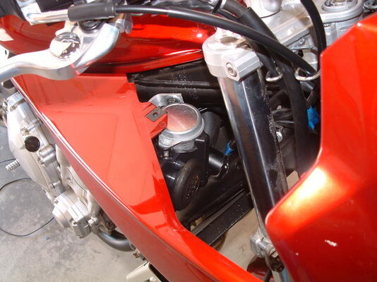
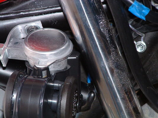
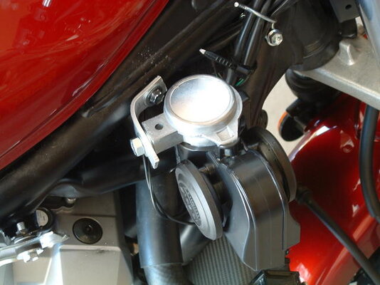
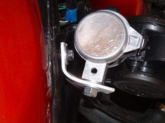
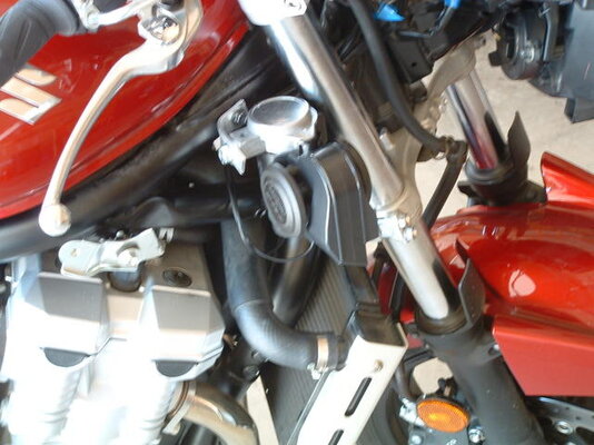
I did a low-tech mount of the horn unit - I added some double stick tape to one edge and then tie-wrapped it with 11" ties to the forward frame piece. It wobbles a little and I'll see it a bracket is in its future after it sees a little road time. There is an extra piece of double stick tape at the bottom to try to keep the tie-wraps from slipping.

d70_5163q.jpg


rightside_5164q.jpg


Final connections were to add crimp lugs to the various wires and connect them: Yellow wire from the aux fuse panel (fused lug) to pin 30 on the airhorn relay. Another 14 gauge yellow wire from pin 87 to the + lug on the horn. The 14 gauge ground wire went to the - lug on the horn. The horn relay was found (it was the only one with pin 30 of the relay at 0 volts with the key on) and the pin 87 wire tapped with a Posi-tap - that wire went to pin 85 on the air horn relay. Pin 86 on the air horn relay got the remaining ground wire.

I now double checked all the wires, made sure two fuses were in the chain (30 at the battery, 20 in the new aux fuse panel).

key on - pressed horn button and got the old wimpy horn
motor started, pressed horn button and waited for ears to stop ringing.

30 seconds later, the wife comes out on the patio and says "I heard it!"

looks like a sucessful test!
righton.gif


Hope this helps somebody. Again, thanks to the Modern Vespa folks that have already contributed to this thread - it was a great starting point!

-------

summary of wire connections:

power to aux fuse panel:
battery +12 to inline fuse to pin 30 of motor-on relay.
pin 87 of motor-on relay to main common lug on aux fuse panel.

control of motor-on relay:
tapped from headlight relay pin 87 to pin 85 of motor-on relay.
ground wire (frame) to pin 86 of motor-on relay.

horn power
from 20 amp fuse lug on aux fuse panel to pin 30 on air horn relay
from pin 87 on air horn relay to + lug on air horn
ground (14 gauge) to - lug on air horn

horn control
tapped from existing horn relay pin 87 to pin 85 of air horn relay.
ground wire (frame) to pin 86 of air horn relay.

-------

This procedure should work with Stebel Nautilus as well - watch the polarity on the horn itself - it is a pitiful horn if reversed...

------- some MP3 notes on wiring (a response)

Other than running the wires, the trick is finding which 2 of the 4 relays under the front cowl to use. These relays are all identical and their position may be different (my leftmost may be different from yours). However, all 4 do the same function on each bike.

I used a voltmeter to check the output of the relays. You want to test the voltage on pin 87 on each relay. Pull one relay out and see where pin 87 is. Then use a voltmeter to test each one.

If I remember correctly, I tested pin 30 on each one first. With the key on, 3 relays have +12 volts on them and one has zero - that is the horn relay. I don't remember if there is a voltage with the key off.

With the key on (motor not running), all pin 87 voltages should be zero - the lights are off and the horn is silent. Start the motor and whichever lights are selected should turn on. Check each pin 87 for +12 volts. I found that 2 of the relays showed +12 with the light switch in either high or low beam. Use one of these to control the motor-on relay.

The suspected horn relay pin 87 should still show zero volts with the motor running. Press the horn button and make sure that you get 12 volts on that relay's pin 87. Use that relay to control the air horn relay.

The advantage of this setup is that you don't have to go fishing for the OEM horn wires. The main problem is routing battery power - be sure and use an inline fuse at the battery for this power wire.

:rider:
 
That is what I have heard but I haven't seen any real proof.

Well, other than the decibels that Bad Boy puts out! :eek2:

Well, I'm just going off what I have seen of them. I was checking them out pretty closely at Pep Boys when I was working on my horn project. They look exactly the same in every detail except for some labeling. But, I suppose there could be a slim chance not. As my wife will tell you (rather emphatically), I've been wrong before.:rider:
 
Greg - Did you use the pre-wired harness or did you simply hook up the Suzuki wiring directly to the Stebel?

Phil,
Sorry but I didn't see the post earlier. I used black zip-ties and ran my wires across the front of the underside of the fuel tank then along the frame tube back to the battery compartment.
 
This is very helpful, Indy! I'm getting ready to install my Nautilus this week and I appreciate the time you took to post this information. :-P
 
Greg - Did you use the pre-wired harness or did you simply hook up the Suzuki wiring directly to the Stebel?

Use the Zook horn wiring to trigger the relay. The high current draw of the Stebel will fry the horn button if you try to use the stock wiring to power the horn.. See this link for the Strom... http://11109.rapidforum.com/topic=110273284421 The wiring diagram works as a guide for most installations. A fuse block is not needed.

A Stebel should be one of the first farkles added. High benefit to $ ratio.
 
If only consumers could avail themselves to A PAIR of loud air horns in complimentary tones. I prefer the sound of dual tone horns, as they just seem to assert themselves with more authority than a single tone horn.

I haven't heard this Stebel Nautilus, but I can tell you that my buddy's BMW RT with it's OEM dual-tone horns is easily mistaken for that of an Angry Buick!
 
Chuck, where did you order your assortment of Posi-Taps? I haven't found a good place to get them, and I'm not paying the NAPA price for another set again.
 
Chuck, where did you order your assortment of Posi-Taps? I haven't found a good place to get them, and I'm not paying the NAPA price for another set again.

I got them from the Posi-Lock site - here. Check their on-line store.
 
If only consumers could avail themselves to A PAIR of loud air horns in complimentary tones. I prefer the sound of dual tone horns, as they just seem to assert themselves with more authority than a single tone horn.

I haven't heard this Stebel Nautilus, but I can tell you that my buddy's BMW RT with it's OEM dual-tone horns is easily mistaken for that of an Angry Buick!

The nautilus is dual-tone - it sounds like an F250! :thumb:
 
If only consumers could avail themselves to A PAIR of loud air horns in complimentary tones. I prefer the sound of dual tone horns, as they just seem to assert themselves with more authority than a single tone horn.

I haven't heard this Stebel Nautilus, but I can tell you that my buddy's BMW RT with it's OEM dual-tone horns is easily mistaken for that of an Angry Buick!

I've got two of the TM80s from this place on my bike. They're LOUD. And dual tone :-)
 
As I mentioned earlier in this thread, I had a Stebel Nautilus installed on my Honda Nighthawk. The Nighthawk, sadly, was wrecked this summer. Instead of letting the insurance benefit from my hard work, I took it off the bike before I let them run off with it to the boneyard. Since I got my 919, I've wanted to get it on there. That pathetic excuse for a horn that came with it was just plain dangerous. So, this past weekend, I went about getting it installed.

Typically what you see with a Stebel install is the compressor and horn unit all mounted together in one tidy package. Tidy as in all together, but that doesn't mean it necessarily LOOKS tidy. In fact, they look rather obnoxious to me. So it was my intent on my 919 to go against the grain and make it less visible. What I did was take the horn off of the compressor. Once I did this, I cut off most of the "ears" of the horn that wrap around the compressor. I left enough (by accident, actually) to drill holes in and run zipties through. I then bought about 5 feet of 5/16" ID fuel line from Lowes. I bought fuel line because 1) it was black and would blend, 2) because I knew it was going to be in close proximity to the engine, and therefore would end up a little warm. Below is what I started with:

2922871505_efe30e2e4f_b.jpg


I took the horn itself and mounted it to the tube that goes in front of the engine and behind the exhaust that you are supposed to mount your frame sliders to (my next project, hopefully). The hose attaches to the horn via a brass 5/16" plumbing barb that was press fitted into the original port that the compressor blows air into. I wasn't to sure how well the horn would hold up to the heat, but so far I haven't had any problems after about 60 miles and a few 100+ mph streaks. (note: this writeup was originally posted on another forum, since I posted this, I've put about 300 miles on the bike with no noticeable issue from the heat) If you look really close, you can see where the horn is behind the exhaust here:

2923721472_389be10a4d_b.jpg


As you can tell, the horn is MUCH less obtrusive than the standard install on a naked bike. Or at least it is to me. Since this picture was taken, I have removed the stock horn. Originally I wanted to have both horns function at the same time, but I decided not to mess with the wiring of it. If you look closely at that picture, you should be able to see the fuel line running from the horn. I routed that up over the engine, under the tank and into a space on the left side of the bike under the seat. This picture might clear it up for you where it goes:

2923721720_1eb1f953ba_b.jpg


As you can see, the fuel line runs into this area and connects to the compressor that was originally attached to the horn. I have zip tied the exhaust port extension back onto the compressor just because I had read where someone else did this and it seemed like a good idea. I installed the compressor in this empty space using a rubber band like thing that I'm not sure what it's original OEM use was supposed to be. I'm assuming that it's actually there for a reason, but for me, it was there to hold down my compressor.

(NOTE: The manufacturer recommends that the compressor be mounted in a vertical position no more than 15 degrees off of vertical. Obviously I have not followed this recommendation. I don't know how this will affect the compressor and any damage that is caused is my own problem. If you choose to follow my lead, and damage that is caused by you mounting your compressor this way is YOUR problem. )

I mounted the relay with super strong double sided tape to an area just above the battery box. You can ALMOST make it out in this picture (sorry, decided to take this picture after everything was back together again).

2922871301_ecbfa32209_b.jpg


In all, I think it turned out to be a fairly clean install. Unless you are looking for it, you'd never know I have this horn installed on my bike. I like to keep things hidden like that. Even more, I like to roll up on pedestrians walking down the sidewalk and blast the daylights out of them. I'm a mean guy.

Hope this helps someone else wanting to install this horn.

Beardking
 
I have installed one in the past on an old 750Four.

The only thing I've read that's missing is the use of Liquid Electrical Tape whenever possible at connections (soldered is best). It comes in different colors too.
 
If you mount them with the intake or the horns facing the wrong direction they can build up gunk in them and eventually die.

Well, I'm just going off what I have seen of them. I was checking them out pretty closely at Pep Boys when I was working on my horn project. They look exactly the same in every detail except for some labeling. But, I suppose there could be a slim chance not. As my wife will tell you (rather emphatically), I've been wrong before.

I bought a "Bad Boy" horn before they started putting those chrome accents on them and at that time it was simply just a sticker that said bad boy on it. I peeled off the sticker and under it was the stebel marks. They are the same horn though and through just labeled differently.
 
If you mount them with the intake or the horns facing the wrong direction they can build up gunk in them and eventually die.

It's mounted correctly.


I bought a "Bad Boy" horn before they started putting those chrome accents on them and at that time it was simply just a sticker that said bad boy on it. I peeled off the sticker and under it was the stebel marks. They are the same horn though and through just labeled differently.

Good to know - that's for reminding me.
 
Have you contacted Stebel for support? They may have some suggestions on how to cure the problem.
 
Back
Top